As a ham radio operator, you may already know that ICOM IC-7300 is one of the most popular radio rig in the world. In addition to this, you may be one of the users of this community, and may have used this radio equipment. On the other hand, due to the lack of RF output support capabilities of IC-7300, you may feel restricted to use SDR receivers such as AirSpy, HackRF, RTL-SDR, SDRplay and software like HDSDR, SDRuno, SDRSharp, GNURadio as well. To solve this problem, we introduce a unique solution by designing a high impedance signal probing product PTRX-7300 to help ham radio operators utilize their IC-7300 with full SDR functionality.
For detailed installation manual, please click here.
PTRX-7300 utilizes an active high impedance current-feedback probing technique to probe bidirectional TX/RX signal line of IC-7300 (J1431). Due to the high impedance nature of the unit, it doesn’t introduce any insertion loss. Therefore there are no adverse effects on the radio side in terms of signal quality. In this method, there isn’t any 3dB insertion loss as in power splitting approach to probe the signal. You can see the block diagram in Figure.1.
Figure. 1: PTRX-7300 block diagram.
During the design phase, we first measured the dynamic range of the TX/RX line (J1431) of IC-7300 in terms of both voltage and frequency. We extracted this information, used it to define the design specification of the unit, and finally developed the proof of concept designs with the help of SPICE simulations. In these simulations, we took into account both the signal integrity and amplification characteristics. With the help of DDS-based signal generator (30kHz to 120MHz, @980mVpp), we analyzed the signal quality both in time and frequency domain.
Our high impedance probe has been designed with components from reputable distributors, such as Digi-Key in order to maintain the highest level of component quality. One of the major observations during testing of the unit was to see that the input/output MCX connectors have a vital role to generate a signal which is free from distortion and attenuation. Please look at Figure.7 for the design and quality details. Any counterfeit/low quality MCX connectors result in extremely poor signal quality. The proof of concept design regarding the development of the unit can be seen in Figure.3.
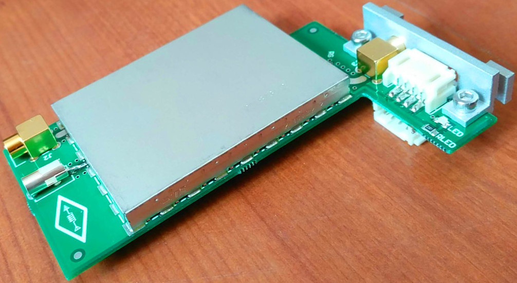
Figure. 2: Actual PTRX-7300 set.
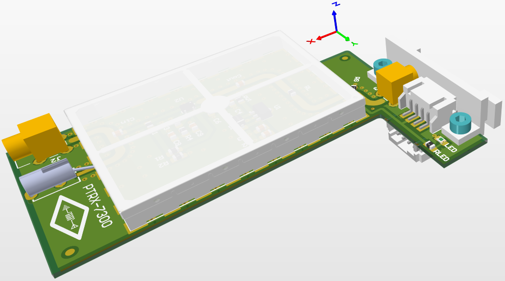
Figure. 3: CAD model of PTRX-7300.
PTRX-7300 does not compromise external tuner functionality. That is, the schematics and the mechanical model have been designed for IC-7300 external tuner opening, which means that you can still continue using your existing external tuner along with the unit.
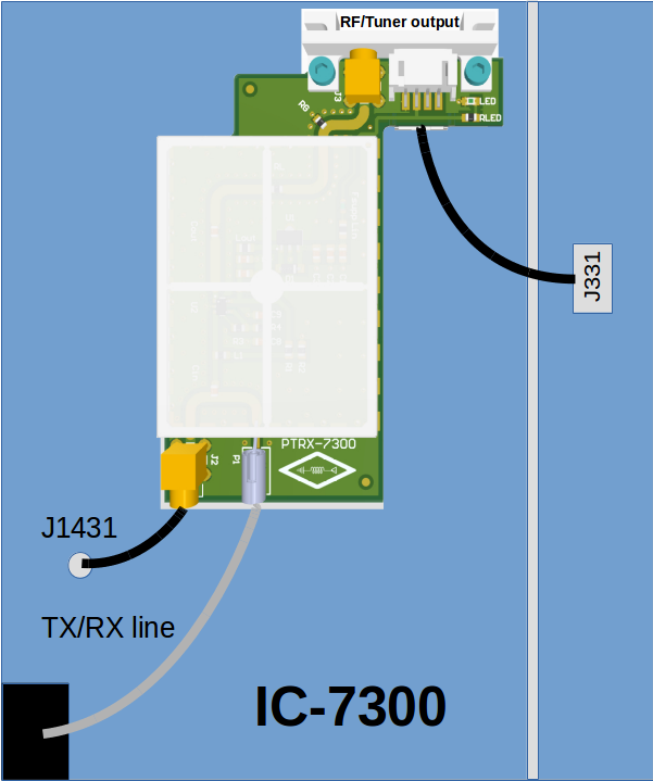
The unit bypasses the external tuner cables to outside, so you keep the functionality of the external tuner signals. It requires 13.8V DC to operate. For this reason, we utilize the power rails from the external tuner cable to supply the unit without adding any external power source. It consumes up to 30mA from external tuner cable so it does not disturb your tuner operations. You can see the details in Figure.4.
Figure. 4: Installed PTRX-7300.
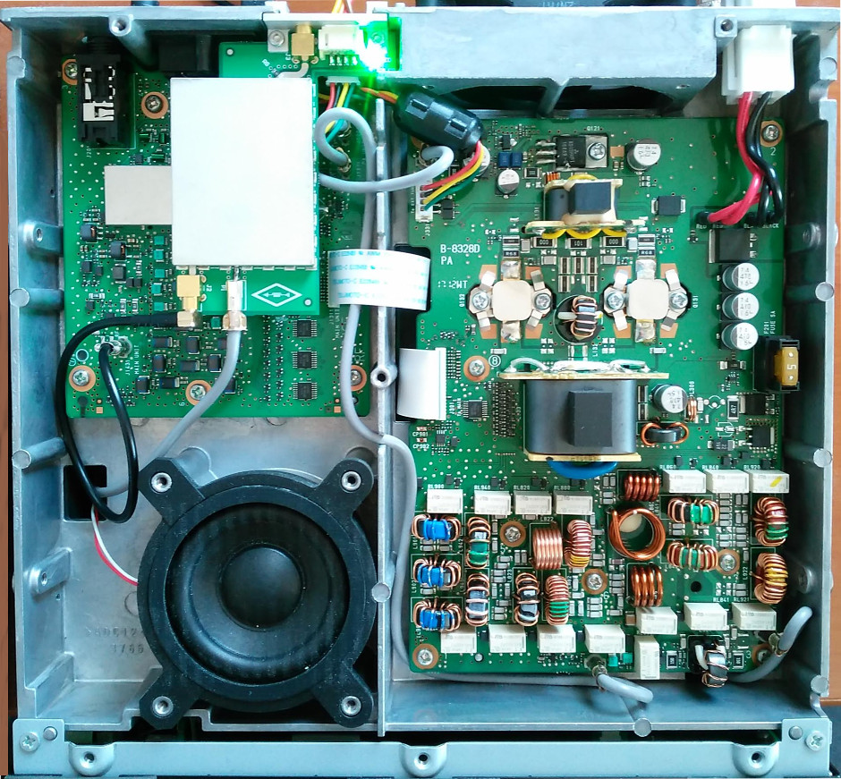
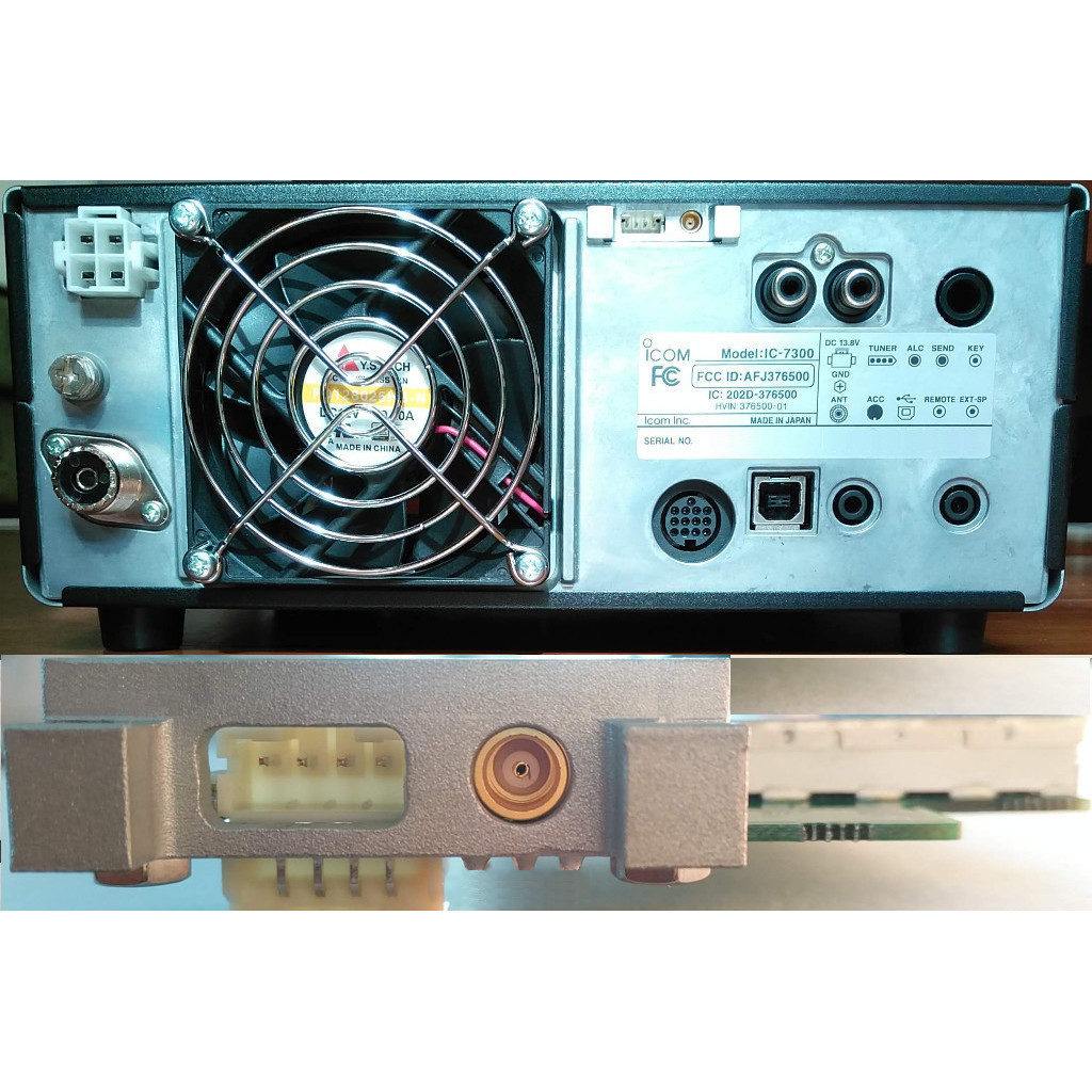
Figure. 5: Rear view of installed PTRX-7300 into IC-7300.
VALIDATION PROCESS
As we mentioned before we applied variable test signals in order to simulate extreme conditions. IC-7300 can operate within the frequency range of 30kHz – 74.8MHz (up to 500mVpp), but we conducted our tests for ranges varying from 30kHz to 120MHz (@980mVpp). We make sure that the unit has flat frequency response for this range.
Our test also covers AM and DRM demodulation on actual HF band conditions. Testing CAT control synchronization with SDR software has been done by OmniRig with HDSDR.